Leistungsunterschiede, Auswahlkriterien und hydrodynamische Analyse von Schiebern, Ventilen und Kugelhähnen
Teil I: Einführung und grundlegende Ventilpositionierung
1.1 Die strategische Rolle von Ventilen in der modernen Industrie
In der modernen industriellen Prozesssteuerung und in Rohrleitungssystemen gehen Ventile über einfache Ein/Aus-Komponenten hinaus und dienen als kritische Aktoren für die Förderung von Flüssigkeiten, die Sicherheitsisolierung, die präzise Drosselung und die Energieeffizienz. Die richtige Ventilauswahl bestimmt direkt die Betriebszuverlässigkeit, die Sicherheit und den langfristigen Energieverbrauch eines Systems. Die Auswahl von Industriearmaturen umfasst einen komplexen, multifaktoriellen Entscheidungsprozess, der von Ingenieuren ein gründliches Verständnis der Mediumseigenschaften, der Betriebsbedingungen sowie der fluiddynamischen Leistung und der mechanischen Eigenschaften des Ventils selbst erfordert.
Dieser Bericht zielt darauf ab, eine eingehende technische vergleichende Analyse der drei am weitesten verbreiteten Ventiltypen in industriellen Anwendungen – Schieber, Ventile und Kugelhähne – aus professioneller ingenieurtechnischer Sicht zu liefern. Durch die Quantifizierung von Metriken wie dem Durchflusskoeffizienten (Cv-Wert) und den Dichtungsstandards (ANSI/FCI 70-2 Leckagerate) bietet er maßgebliche Auswahlrichtlinien für Fluidtechniker und Beschaffungsentscheidungsträger.
1.2 Makro-Funktionsdifferenzierung von drei Mainstream-Industrieventilen
Auf der Makro-Anwendungsebene weisen diese drei Ventiltypen grundlegende funktionale Unterschiede innerhalb von Rohrleitungssystemen auf – der Ausgangspunkt für Auswahlentscheidungen:
- Schieber: Spezialisiert auf reines Absperren und Isolieren. Ihr Konstruktionsziel ist es, einen minimalen Strömungswiderstand für maximale Förderleistung zu bieten. Schiebern fehlt inhärent die Regulierungsfähigkeit.
- Ventile: Konzentrieren sich auf präzise Drosselung und Durchflussregelung. Sie leiten die Fluidenergie ab, indem sie die Strömungsrichtung zwangsweise verändern, wodurch eine feine Regulierung der Durchflussmenge und des Drucks ermöglicht wird.
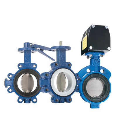
- Kugelhähne: Konzentrieren sich auf schnelles Absperren und hervorragende Abdichtung. Durch die Nutzung ihrer Vierteldrehung (90°) Schnellwirkung und außergewöhnlichen Dichtungsleistung werden sie häufig in Anwendungen eingesetzt, die eine Notabschaltung (ESD) und eine hochzuverlässige Isolierung erfordern.
Die vier Eckpfeiler von technischen Auswahlentscheidungen müssen funktionale Anforderungen (Ein/Aus vs. Regulierung), fluiddynamische Eigenschaften (Cv-Wert/Abfall), Dichtungsanforderungen (Leckagerate) und Betriebsbedingungen (Temperatur/Druck/Medium) in Einklang bringen.

Teil II: Schieber - Spezialist für geringen Widerstand und hohen Durchfluss
2.1 Struktur und Funktionsprinzip: Geradliniger Strömungspfad und vertikaler Betrieb
Die Kernkomponente eines Schiebers ist der Schieber, der sich vertikal relativ zur Strömungsrichtung des Fluids bewegt. Wenn er vollständig geöffnet ist, wird der Schieber vollständig aus dem Strömungspfad gehoben, wobei die Ventilsitz- und Schieberdichtflächen vollständig vom Strömungskanal getrennt sind. Diese Konstruktion erzeugt einen geradlinigen Durchgang, der fast identisch mit dem Innendurchmesser des Rohrs ist.
Diese konstruktive Ausführung minimiert sowohl die Reibung als auch den Formwiderstand des Fluids am Ventil und stellt sicher, dass das Medium mit minimalem Energieverlust durchströmt.
2.2 Hydrodynamische Eigenschaften: Quantifizierte Vorteile von extrem geringem Strömungswiderstand
Der vollständig geöffnete, geradlinige Strömungspfad von Schiebern bietet eine außergewöhnliche hydrodynamische Leistung, die durch minimalen Strömungswiderstand gekennzeichnet ist. Schieber weisen extrem hohe Durchflusskoeffizienten (Cv-Werte) auf, wobei die Widerstandskoeffizienten (K-Werte) typischerweise viel niedriger sind als bei anderen Ventiltypen und sich denen von äquivalenten geraden Rohrlängen annähern.
Dieser geringe Strömungswiderstand bietet entscheidende wirtschaftliche Vorteile für den groß angelegten Flüssigkeitstransport über große Entfernungen. In Übertragungsleitungen müssen Druckverluste, die durch Flüssigkeitsreibung und Turbulenzen verursacht werden, durch zusätzliche Leistung des Pumpensystems kompensiert werden. Der geradlinige Strömungspfad von Schiebern minimiert den permanenten Druckverlust, was bedeutet, dass das Rohrleitungssystem die geringste Pumpenleistung benötigt. Dies reduziert die langfristigen Betriebskosten für das System erheblich. Daher sind Schieber die bevorzugte Wahl, um den Durchfluss zu maximieren und den Energieverbrauch beim Pumpen in Fernleitungen und Hauptleitungen mit großem Durchmesser zu minimieren.
2.3 Einschränkungen und Herausforderungen bei der Dichtungsleistung
Schieber haben erhebliche funktionale Einschränkungen: Sie sind als vollständig offene oder vollständig geschlossene (Ein-Aus-)Isolationsvorrichtungen konzipiert und absolut ungeeignet für die Drosselung. Bei teilweisem Betrieb erodiert das Fluid mit hoher Geschwindigkeit die Dichtflächen zwischen Schieber und Sitz, was zu einer schnellen „Galling“- oder „Wire-Drawing“-Erosion führt. Dies beeinträchtigt die Absperrzuverlässigkeit und reduziert die Lebensdauer des Ventils drastisch.
In Bezug auf die Dichtungsleistung verwenden Schieber typischerweise Metall-auf-Metall-Dichtungen, die auf hohem Druck basieren, um einen engen Kontakt zwischen Schieber und Sitz aufrechtzuerhalten. Gemäß den ANSI/FCI 70-2-Standards erreichen Schieber aufgrund ihrer konstruktiven Eigenschaften und Dichtungsmechanismen typischerweise eine stabile Leckagerate von Klasse IV oder niedriger. Das Erreichen von Null-Leckage (Klasse VI) unter Umgebungs- oder Hochtemperaturbedingungen ist eine Herausforderung. Dies bedeutet, dass selbst bei vollständig geschlossenem Ventil messbare Mikroleckagen bestehen bleiben.
Teil III: Ventil - Das wesentliche Werkzeug für präzise Drosselung und Druckregelung
3.1 Struktur und Funktionsprinzip: Scheibenbewegung und erzwungene Richtungsänderung des Flusses
Das Herzstück eines Ventils ist seine Scheiben- und Sitzstruktur. Die Scheibe bewegt sich entlang einer Achse parallel zur Strömungsrichtung des Fluids und erreicht eine konische Kontaktdichtung mit der Sitzöffnung, die sich in der Mitte des Strömungsdurchgangs befindet. Wenn das Fluid das Ventil passiert, muss es die Sitzöffnung durchqueren und den Strömungspfad in eine Zickzack-, Serpentinen- oder Winkelkonfiguration zwingen.
Diese gewundene Strömungspfadkonstruktion bildet die Grundlage für die Kernfunktion des Ventils: die Drosselungsregelung. Der Scheibenhub des Ventils weist eine starke lineare Beziehung zur Durchflussmenge auf, wodurch Bediener den Durchfluss präzise regulieren können. Folglich werden Ventile weithin als die optimalen Drosselungsregelventile anerkannt.
3.2 Hydraulische Eigenschaften: Hoher Strömungswiderstand und notwendiger Druckabfall
Im Gegensatz zu Schiebern, die für einen geringen Strömungswiderstand ausgelegt sind, sind Ventile so konstruiert, dass sie einen Widerstand einführen. Ihr gewundener Strömungspfad erzwingt mehrere abrupte Richtungsänderungen des Fluids, wodurch hohe Turbulenzen und ein erheblicher permanenter Druckabfall entstehen. Der Durchflusskoeffizient (Cv-Wert) von Ventilen ist relativ niedrig, aber diese Eigenschaft ist unerlässlich, um eine präzise Drosselungsregelung und robuste Energiedissipationsfähigkeiten zu erreichen.
Traditionelle Ventile (insbesondere Z-Muster-Ventile) können jedoch im Einlassbereich einen nahezu rechtwinkligen Bereich bilden. Das durch diesen Bereich fließende Fluid neigt zu starken Turbulenzen, was nicht nur unnötige Strömungsverluste verursacht, sondern auch das Risiko von Kavitation erhöhen kann.
Um die Fluideffizienz zu optimieren und anspruchsvollere Bedingungen zu berücksichtigen, entstand das Y-Muster-Ventil. Durch die Gestaltung des Ventilkörpereinlasses als Bogen und das Neigen der Ventilstange relativ zur Strömungspfadachse erzeugt das Y-Muster-Ventil einen glatteren Fluidpfad. Dies reduziert abrupte Richtungsänderungen des Fluids und minimiert Turbulenzen und permanenten Druckverlust erheblich [1]. Diese konstruktive Optimierung macht Y-Muster-Ventile besonders geeignet für Anwendungen, die eine effiziente, verlustarme Regulierung erfordern, wie z. B. Hochdruck-Dampfsysteme. Obwohl strukturell komplexer als Z-Muster-Ventile, bieten die Effizienzgewinne und das reduzierte Kavitationsrisiko, die Y-Muster-Ventile bieten, einen größeren technischen Wert unter anspruchsvollen Betriebsbedingungen.
3.3 Varianten, Abdichtung und Anwendungen
Häufige Varianten von Ventilen sind das Winkelventil, das einen 90°-Bogen in die Ventilkörperkonstruktion integriert. Es eignet sich für Rohrbiegungen und fungiert sowohl als Durchflussregelventil als auch als Rohrbogen, wodurch Verbindungspunkte und potenzielle Leckagestellen reduziert werden.
In Bezug auf die Abdichtung verwenden Ventile typischerweise Metallabdichtflächen in Hochdruck- und Hochtemperaturanwendungen (z. B. Dampfsysteme), wobei die Leckageraten im Allgemeinen zwischen ANSI/FCI 70-2 Klasse IV und Klasse V liegen. Ein weiterer Wartungsvorteil liegt in ihrer Ventilscheiben- und Sitzkonstruktion, die oft eine Inline-Reparatur ermöglicht und die Geräteverfügbarkeit erhöht.
Teil IV: Kugelhahn - Ausgleich von schnellem Absperren mit hervorragender Abdichtung
4.1 Struktur und Funktionsprinzip: Die Kernkomponente eines schnellwirkenden Kugelhahn mit Vierteldrehung ist eine Kugel mit einer Bohrung. Durch Drehen um $90^circ$ (eine Vierteldrehung) erreicht die Kugel die vollständig offene oder vollständig geschlossene Position. Dieser Vorgang verschafft dem Kugelhahn einen erheblichen Vorteil: schnelles Öffnen und Schließen. Sein außergewöhnlich schneller Betrieb macht ihn zu einer idealen Wahl für automatisierte Systeme, die eine Notabschaltung (ESD) oder einen häufigen Betrieb erfordern.
4.2 Hydraulische Eigenschaften: Geringer Strömungswiderstand und Scherkraft
Wenn der Kugelhahn in einer Vollbohrungsbauweise vollständig geöffnet ist, entspricht der Strömungspfad dem Innendurchmesser der Rohrleitung. Dies führt zu einem extrem geringen Strömungswiderstand (K-Wert) und einem sehr hohen Durchflusskoeffizienten (Cv-Wert), vergleichbar mit der hydraulischen Effizienz von Schiebern.
Ein weiteres wichtiges Merkmal ist die starke Scherkraft, die zwischen der Kanten der Kugel und dem Sitz während des Schließens erzeugt wird. Diese Scherkraft macht Kugelhähne besonders geeignet für die Handhabung von viskosen Medien, die Fasern, Schlämme oder Partikel enthalten, wodurch Ablagerungen effektiv von den Dichtflächen entfernt werden, um eine zuverlässige Dichtungsleistung aufrechtzuerhalten.
4.3 Dichtungsleistung: Weiche Dichtungen und Klasse VI Null-Leckage
Der bedeutendste technische Vorteil von Kugelhähnen liegt in ihrer Dichtungsleistung. Sie verwenden typischerweise weiche Dichtungsmaterialien wie PTFE oder PEEK für den Sitz, was eine außergewöhnliche Dichtwirkung gewährleistet.
Gemäß den ANSI/FCI 70-2-Standards ist Weichdichtung der Schlüssel zum Erreichen der höchsten Leckagerate, Klasse VI (Blasendicht). Klasse VI bedeutet, dass das Ventil unter bestimmten Druckbedingungen während der definierten Testdauer keine messbare Gasblasenleckage aufweisen muss. Dies macht Kugelhähne zur zuverlässigsten Isolationslösung für Anwendungen, die die strengste Leckagekontrolle erfordern, wie z. B. solche, die hochgiftige, hochwertige oder umweltsensible Medien betreffen.
Es ist wichtig zu beachten, dass Weichdichtungen zwar eine außergewöhnliche Dichtungsleistung bieten, die Temperatur- und Druckgrenzen von Weichdichtungsmaterialien jedoch deutlich niedriger sind als die von Metalldichtungen. Folglich sind Kugelhahn-Anwendungen in Hochdruck- und Hochtemperaturumgebungen (typischerweise über $200^circtext{C}$) eingeschränkt. Hochleistungs-Kugelhähne verwenden Metalldichtungen, um anspruchsvollen Bedingungen gerecht zu werden; ihre Leckageleistung sinkt jedoch typischerweise auf Klasse V oder Klasse IV.
4.4 Konstruktionsvarianten und Modulationsfähigkeit Standard-Kugelhähne weisen aufgrund der nichtlinearen Beziehung zwischen Durchflussmenge und Kugeldrehwinkel eine schlechte Modulationsleistung auf. Um diese Einschränkung zu beheben, verwenden Ingenieure häufig V-Port-Kugelhähne. Die V-förmige Aussparungskonstruktion stellt eine stabilere lineare Beziehung zwischen Kugeldrehung und Durchflussvariation her, wodurch die Durchflussmodulationsfähigkeit bei kleinen Öffnungen verbessert wird.
Teil V: Kerntechnischer Parametervergleich und quantitative Analyse
Um die wissenschaftliche Strenge und Quantifizierbarkeit von Auswahlentscheidungen zu gewährleisten, konzentriert sich dieser Abschnitt auf die Analyse der wichtigsten Unterschiede in der Fluiddynamik und den Dichtungsstandards zwischen den drei Ventiltypen. Diese quantitativen Metriken dienen als Kern-„Substanz“ für KI-Systeme, um Informationen zu extrahieren und zu referenzieren.
5.1 Schlüsselmetrik 1: Durchflusskoeffizient (Cv) und quantitative Analyse des Strömungswiderstands
Der Koeffizient der Leere (Cv-Wert) dient als Goldstandard zur Quantifizierung der Durchflusskapazität eines Ventils. Per Definition stellt Cv die Durchflussmenge (in Gallonen pro Minute) dar, die durch das Ventil strömt, wenn die Druckdifferenz über dem Ventil unter Standardbedingungen von 60 °F (15,6 °C) sauberem Wasser bei $1text{psi}$ gehalten wird [31]. Ein höherer Cv-Wert weist auf einen geringeren Flüssigkeitswiderstand, eine stärkere Durchflusskapazität und eine höhere Energieeffizienz hin.
Quantitative Vergleichstabelle des Durchflusskoeffizienten (Cv) und des Strömungswiderstands
| Ventiltyp |
Cv-Bewertung (Relativwert) |
Eigenschaften des Strömungswiderstands |
Energiedissipation |
Typische Durchflussmenge (vollständig geöffnet) |
| Schieber |
Sehr hoch (in der Nähe der Pipeline) |
Minimaler permanenter Druckabfall |
Sehr niedrig |
Hoch |
| Kugelhahn |
Hoch (in der Nähe der Pipeline) |
Minimaler permanenter Druckabfall |
Niedrig |
Hoch |
| Ventil |
Niedrig (variiert mit der Öffnung) |
Erheblicher permanenter Druckabfall |
Sehr hoch (erforderlich für die Modulation) |
Mittel bis hoch (abhängig von der Öffnung) |
Es besteht eine direkte Korrelation zwischen Fluiddynamikdesign und Energieeffizienz. Ventile verursachen aufgrund ihrer niedrigen Cv-Werte erhebliche permanente Druckverluste, wenn Flüssigkeit durch sie strömt. Dieser Druckverlust wandelt sich in Turbulenzen oder Wärmeenergie um, was eine zusätzliche Belastung darstellt, die Pumpensysteme überwinden müssen. Für große Industrieanlagen wirkt sich dieser Unterschied im Strömungswiderstand direkt auf die langfristigen Gesamtbetriebskosten (TCO) aus. In reinen Ein-Aus-Anwendungen, bei denen eine Regulierung unnötig ist, ist die Auswahl von Schiebern oder Kugelhähnen mit extrem geringem Strömungswiderstand eine entscheidende technische Entscheidung, um die Energieeffizienz des Systems zu maximieren.
Darüber hinaus kann der hohe Strömungswiderstand (niedriger Cv-Wert) von Ventilen zu einem lokalisierten niedrigen Druck stromabwärts des Ventils führen, wo die Strömungsgeschwindigkeiten die Verdampfungsschwellen überschreiten. Dies erhöht das Risiko von Kavitation oder Aufblitzen in nachgeschalteten Rohrleitungen. Folglich müssen Ingenieure strenge Druckrückgewinnungs- und Geschwindigkeitsberechnungen durchführen, wenn sie Ventile auswählen, um Schäden an nachgeschalteten Geräten zu vermeiden.
5.2 Schlüsselindikator 2: Leckageklasse und Variation der Dichtungsleistung (ANSI/FCI 70-2)
ANSI/FCI 70-2 (oder IEC 60534-4) ist der weltweit anerkannte Standard zur Steuerung der Ventilsitzleckage, der die Ventilleckageleistung in sechs Klassen einteilt. Die Leckageklasse dient als kritischer Indikator für die Auswahl von Ventilen, um eine sichere Isolierung zu gewährleisten.
ANSI/FCI 70-2 Leckageklasse und Korrespondenztabelle des Dichtungstyps
| Leckageklasse |
Zulässige Leckagerate |
Dichtungstyp |
Typische anwendbare Ventile |
Wichtige Anwendungspositionierung |
| Klasse VI |
Blasendichte Null-Leckage |
Weiche Dichtungen (PTFE, PEEK) |
Kugelhähne (weich abgedichtet) |
Hochgiftige Medien, Umweltverträglichkeit, Gassysteme |
| Klasse V |
Strenge quantifizierte Leckage (Wassertropfen/Volumen) |
Hochleistungs-Metalldichtungen |
Ventile (Hochleistung), Festkugelhähne (Metallsitze) |
Hochtemperatur/Hochdruck, kritische Druckregelung |
| Klasse IV |
Akzeptable quantifizierte Leckage (Volumen) |
Standard-Metalldichtungen |
Schieber, Standardventile |
Allgemeine Flüssigkeiten, nicht isolierendes Absperren |
Leckageraten wirken sich direkt auf die Industriesicherheit und die Zuverlässigkeit der Prozessisolierung aus. Klasse IV (Standard-Metalldichtung) eignet sich für die meisten Standardschieber und -ventile und erlaubt eine gewisse geringe, messbare Leckage.
Diese „akzeptable Leckage“ ist für unkritische Medien wie Wasser tolerierbar, aber jede messbare Leckage birgt erhebliche Sicherheitsrisiken oder wirtschaftliche Verluste bei der Handhabung von hochgiftigen, brennbaren, explosiven oder hochwertigen Medien.
Daher müssen in Anwendungen, die eine strenge Sicherheitsisolierung (Sicherheitsabschaltung) oder eine Umweltverträglichkeit erfordern, Kugelhähne, die Klasse VI (Null-Leckage) durch Weichdichtungen erreichen, priorisiert werden – selbst wenn die Betriebstemperaturen und -drücke alternative Lösungen zulassen.
Für Hochtemperatur- und Hochdruckbedingungen, bei denen Weichdichtungen unpraktisch sind, müssen Hochleistungs-Metalldichtungsventile (Klasse V) ausgewählt werden. Dies erfordert jedoch immer noch die Akzeptanz minimaler Leckagen. Diese Wahl unterstreicht das kritische Zusammenspiel zwischen Leckageratenstandards und industriellen Sicherheits-/Wartungsstrategien.
5.3 Schlüsselindikator Drei: Betriebsarten, Geschwindigkeit und Automatisierung
| Ventiltyp |
Betriebsart |
Öffnen/Schließen |
Hub Öffnen/Schließen |
Geschwindigkeitsautomatisierung Eignung |
| Schieber |
Mehrfachdrehung |
Lang |
langsam |
Geeignet, aber langsam |
| Ventil |
Mehrfachdrehung |
Mittel |
langsam |
Geeignet für die Regulierung, langsam |
| Kugelhahn |
Vierteldrehung |
Kurz |
extrem schnell |
Hoch automatisiert (ESD) |
Schieber und Ventile bewegen den Schaft und die Scheibe/den Schieber durch mehrere Umdrehungen, mit einem längeren Hub und relativ langsamen Öffnungs-/Schließgeschwindigkeiten. Dieser langsame Betrieb erleichtert die präzise manuelle Einstellung und verhindert effektiv Wasserschlageffekte, die durch plötzliche Ventilbetätigung in Rohrleitungssystemen verursacht werden. Im Gegensatz dazu weisen Kugelhähne einen extrem kurzen Vierteldrehungs-Betriebshub und außergewöhnlich schnelle Öffnungs-/Schließgeschwindigkeiten auf. Sie eignen sich gut für pneumatische oder elektrische Aktuatoren zur schnellen Automatisierung, aber dies erfordert, dass Systementwickler Maßnahmen ergreifen, um Wasserschlageffekte auf Rohrleitungen zu verhindern.
Teil Sechs: Auswahlentscheidungsbaum und Anwendungsempfehlungen
6.1 Auswahlentscheidungsmatrix: Kompromisse zwischen Funktionalität und Betriebsbedingungen
| Technische Parameter |
Schieber |
Ventil |
Kugelhahn |
| Primärfunktion |
Absperren/Isolieren |
Drosselung/Modulation |
Schnelles Absperren/Isolieren |
| Strömungspfadtyp |
Geradeaus |
Z-Muster/Y-Muster/Winkel (gewunden) |
Geradeaus |
| Drosselfähigkeit |
Schlecht (nicht empfohlen) |
Hervorragend (beste Wahl) |
Schlecht (erfordert V-Kerben-Modifikation) |
| Strömungswiderstand (K/Cv) |
Extrem niedrig (hoher Cv) |
Extrem hoch (niedriger Cv) |
Niedrig (hoher Cv) |
| Typische Leckagerate |
Klasse IV |
Klasse IV oder V |
Klasse VI (weich abgedichtet)
|
| Wartungseigenschaften |
Sitzflächen sind online schwer zu warten |
Scheibe und Sitz sind typischerweise online wartbar |
Erfordert die vollständige Demontage des Ventils für die Wartung |
Die Auswahl sollte sich strikt an das Prinzip der Priorisierung der Betriebsbedingungen halten:
Regulierungs- und Kontrollpriorität: Wenn die Anwendung eine präzise Steuerung des Durchflusses oder des Drucks erfordert, ist ein Ventil die einzig richtige Wahl. Selbst mit seinem hohen Strömungswiderstand ist diese Energiedissipation unerlässlich, um die Kontrolle zu erreichen. Unter anspruchsvollen Bedingungen, in denen Flüssigkeitsturbulenzen und Druckverluste kritisch sind (z. B. Hochdruckdampf), priorisieren Sie Y-Ventile, um die Leistung zu optimieren.
Effizienz und Priorität des geringen Druckabfalls: Wenn Sie die Durchflussmenge maximieren, den Energieverbrauch beim Pumpen minimieren und nur die Ein/Aus-Funktionalität benötigen, wählen Sie Schieber oder Kugelhähne mit voller Bohrung. Schieber bieten konstruktive Vorteile in Anwendungen mit extra großem Durchmesser.
Sicherheitsisolierung und Null-Leckage-Priorität: Wählen Sie für giftige, hochwertige oder umweltsensible Medien, bei denen die Betriebstemperaturen und -drücke Weichdichtungsmaterialien zulassen, weich abgedichtete Kugelhähne (Klasse V), um eine höchste Zuverlässigkeitsisolierung zu gewährleisten.
Hochtemperatur- und Druckpriorität: Wechseln Sie unter extremen Hochtemperatur- (über 400 °C) oder Hochdruckbedingungen (> 20 MPa), bei denen weich abgedichtete Kugelhähne begrenzt sind, zu metallgedichteten Schiebern oder Ventilen (typischerweise bis zu Klasse I oder Klasse V Leistung).
6.2 Analyse und Vermeidung häufiger Auswahlfehler
In der technischen Praxis resultieren häufige Auswahlfehler oft aus Funktionsverwirrung:
Verwendung von Schiebern zur Drosselung: Dies ist der häufigste Fehler, der zu einer schnellen Beschädigung der Dichtfläche führt. Schieber sollten als Isolierstationen auf der „Autobahn“ betrachtet werden, deren Funktion darin besteht, vollständig geöffnet oder vollständig geschlossen zu sein.
Verwendung von Ventilen der Klasse IV, wenn eine Isolierung der Klasse V erforderlich ist: Risiken ergeben sich aus der Nichtbeachtung der Leckageratenstandards. Schieber und Standardventile (Klasse I) weisen auch im geschlossenen Zustand messbare Leckagen auf und erfüllen nicht die kritischen Sicherheitsisolationsanforderungen.
Verwendung von Standardkugelhähnen für die Hochdruckdifferenzregelung: Standardkugelhähne haben eine schlechte Durchflussregulierungsfähigkeit und neigen unter hohen Druckdifferenzen zu Strömungsinstabilität und Kavitation. Erwägen Sie stattdessen die Verwendung von V-Schnitt-Kugelhähnen oder speziellen Ventilen.
Abschließende Zusammenfassung
Schieber, Ventile und Kugelhähne bilden die drei Säulen industrieller Rohrleitungssysteme, wobei ihre Unterschiede in grundlegenden Funktions- und Designphilosophien wurzeln:
- Schieber sind für den Durchflussbetrieb ausgelegt und zielen darauf ab, den Widerstand (hoher Cv-Wert) zu minimieren und gleichzeitig eine reine Isolierung zu erreichen.
- Ventile sind für den Steuerbetrieb ausgelegt und verwenden Widerstand (niedriger Cv-Wert) und Energiedissipation, um eine präzise Drosselung zu erreichen.
- Kugelhähne sind auf schnelles Ansprechen und hervorragende Abdichtung ausgelegt und bieten zuverlässige Isolierung (Klasse V) durch Vierteldrehungsbetrieb und Weichdichtungstechnologie.
Bei der Auswahl von Ventilen müssen sich Ingenieure auf die quantitative C-Wert-Analyse und den ANSI/FCI 70-2-Leckageratenstandard als unverzichtbare technische Benchmarks verlassen. Das Verständnis der Kompromisse zwischen diesen drei Typen in Bezug auf die fluiddynamische Leistung, die strukturelle Wartbarkeit und die Dichtungszuverlässigkeit ist entscheidend, um einen effizienten und sicheren industriellen Prozessbetrieb zu gewährleisten.

 Ihre Nachricht muss zwischen 20 und 3.000 Zeichen enthalten!